Modular River Current Energy Converter
Purdue University & US Department of Energy
Note: Detailed design and drawings are not provided for this project due to an NDA and Intellectual Property Agreements
Introduction
In response to a $26.1 Million grant by the Department of Energy to design and develop hydro-kinetic applications in rivers, the Experimental & Applied Fluid Dynamics Lab at Purdue University entered Phase 1 of detailed conceptual design of the grant to compete against two companies to advance to Phase 2 of prototyping, site testing, and manufacturing.
Low-head hydro-power and hydro-kinetic river current energy converter (CEC) technologies have the potential to generate a significant amount of electricity from the nation’s rivers and to support the resiliency of the U.S electricity system. With current concerns of climate change, this technology would sustainably harness electricity from local sources.
Challenge
The grant focuses on developing and testing CEC systems that can be efficiently deployed and retrieved without the need for significant port or on-site infrastructure and specialized vessels. The system should not adversely affect the marine ecosystem or significantly hinder commercial activities in the river body. Environment-friendly materials should be used in the design and construction of the system including adhesives and lubricants.
Solution
I joined the research team as a Research Fellow responsible for the overall design, development, and manufacturing of the system. The design process began with in-depth customer and competitor analysis, patent identification, brainstorming, concept generation, and an initial design down-selection.
Through literature review, I became familiar with the design practices common in underwater applications for sealing, non-corrosive material selection, tolerances, and computational fluid dynamics. I designed and assembled a 500+ part system in SolidWorks which served as the foundation for our iterative design cycle to perform FEA and CFD simulations, improve theoretical performance, and reduce cost. Several motion studies to observe the effects of gravity on individual components and part interference during operation were prepared using the SolidWorks Simulation package. Upon revisiting our CAD and simulation needs, the team decided to transition to the Siemens environment to take advantage of the NX package linked to their PLM software (Siemens Teamcenter). I completed 40+ hours of Siemens NX training to lead the transfer of our CAD documents between these packages while ensuring their compatibility.
Design & Testing
-
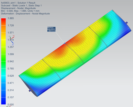
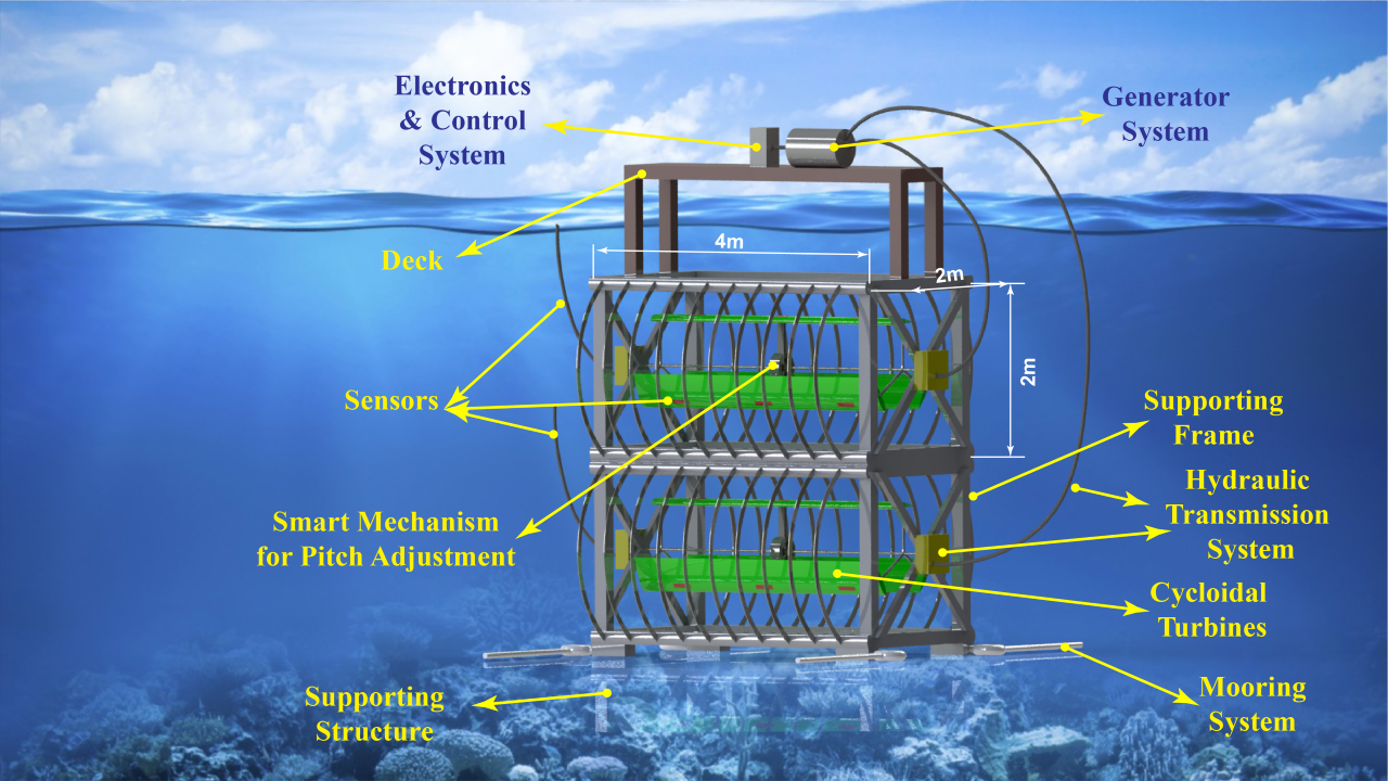
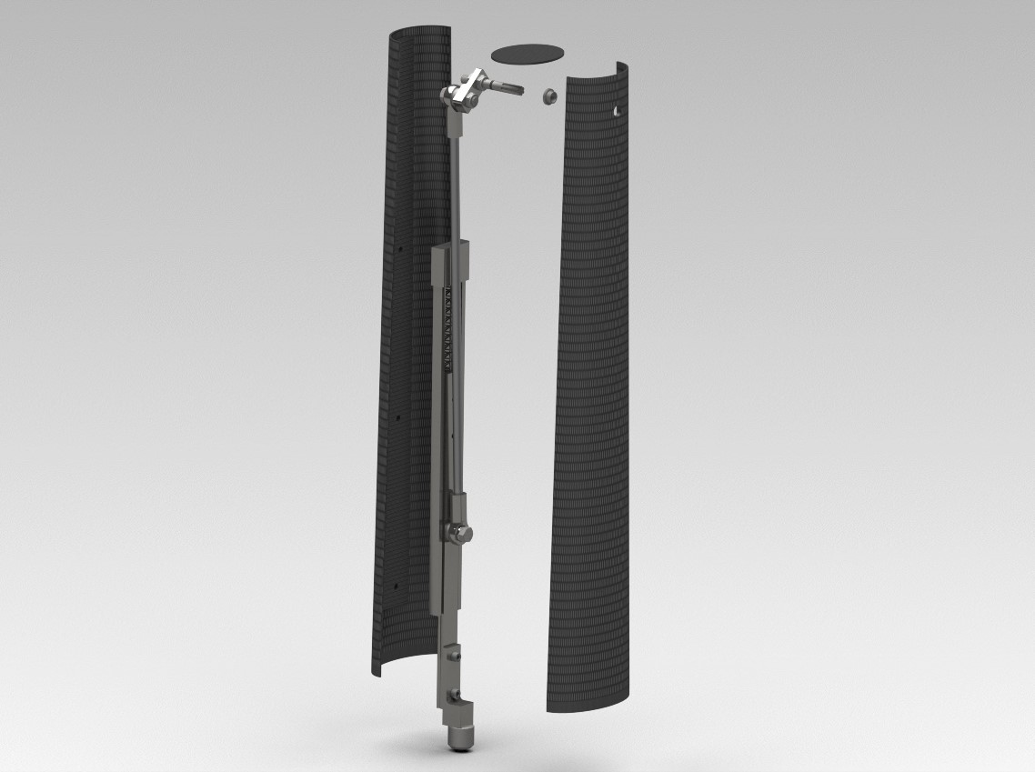
Custom tapered multi-profile NACA hydrofoil designed with iterative results from CFD and FEA results to improve flow of medium and reduce drag by 15%
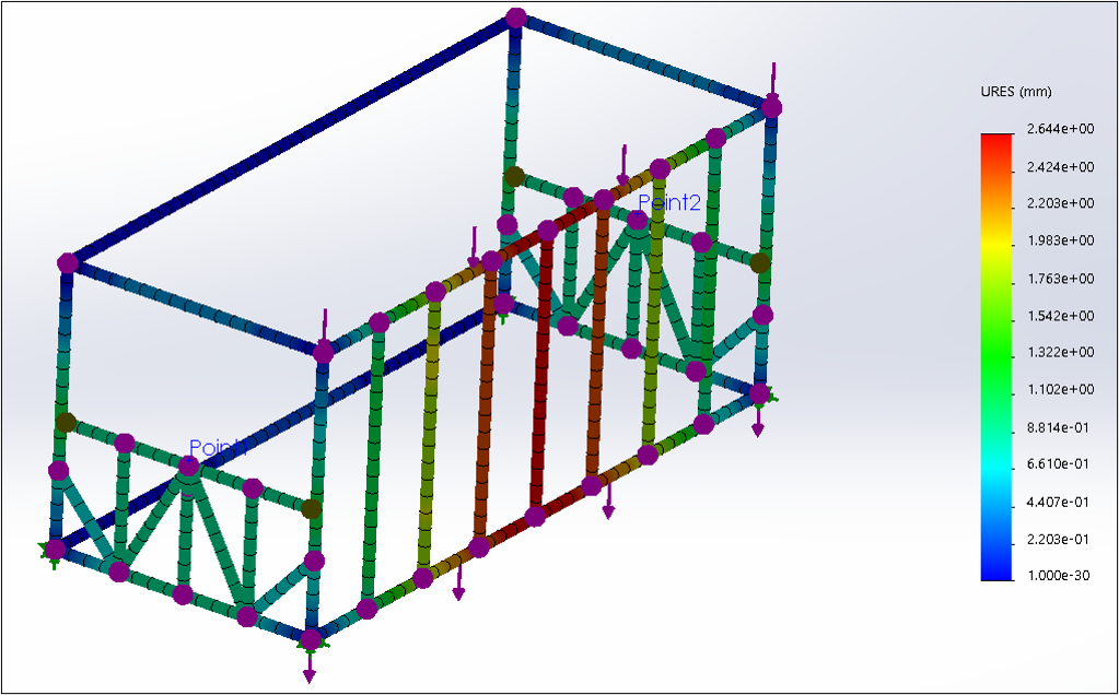
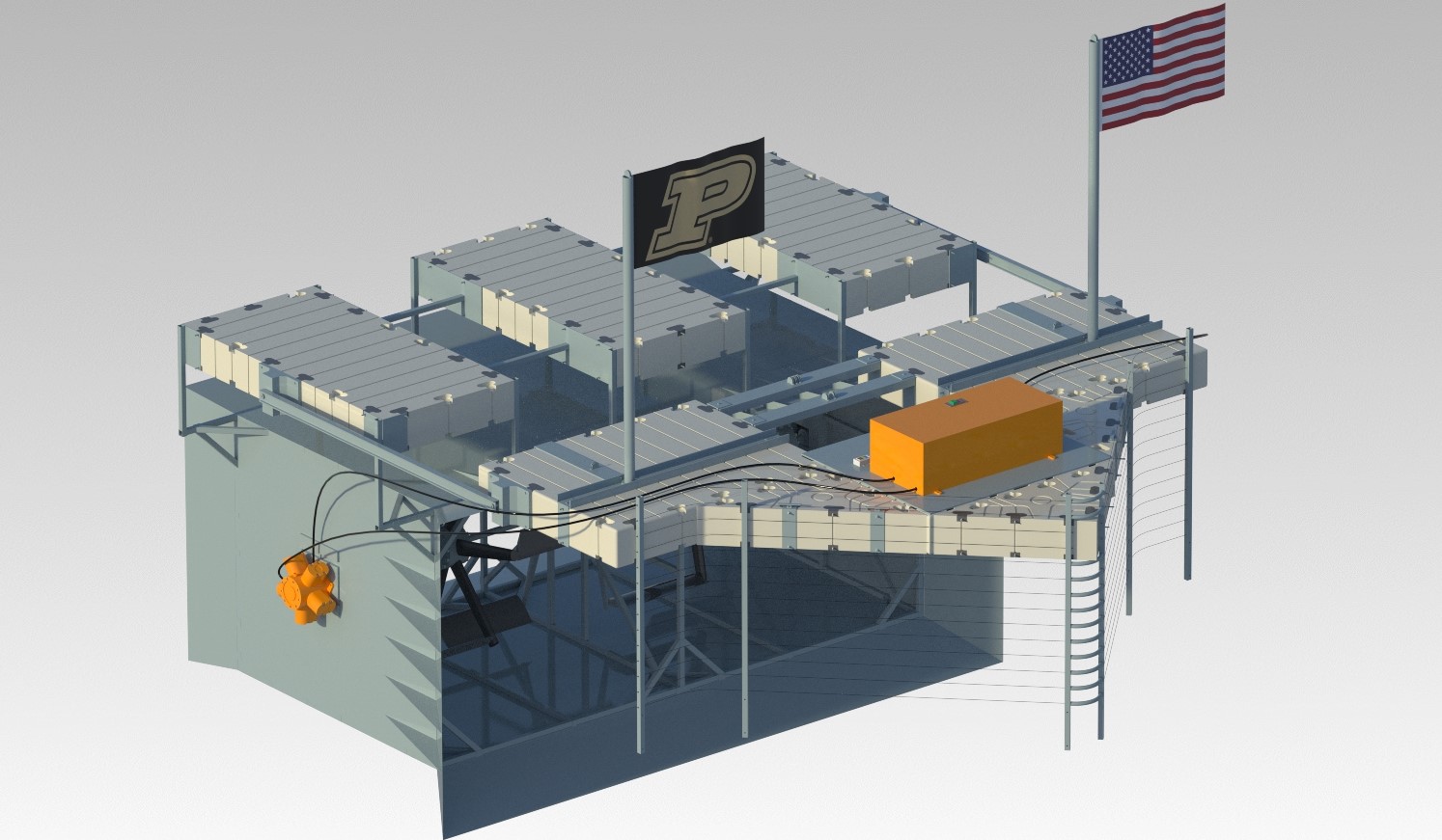
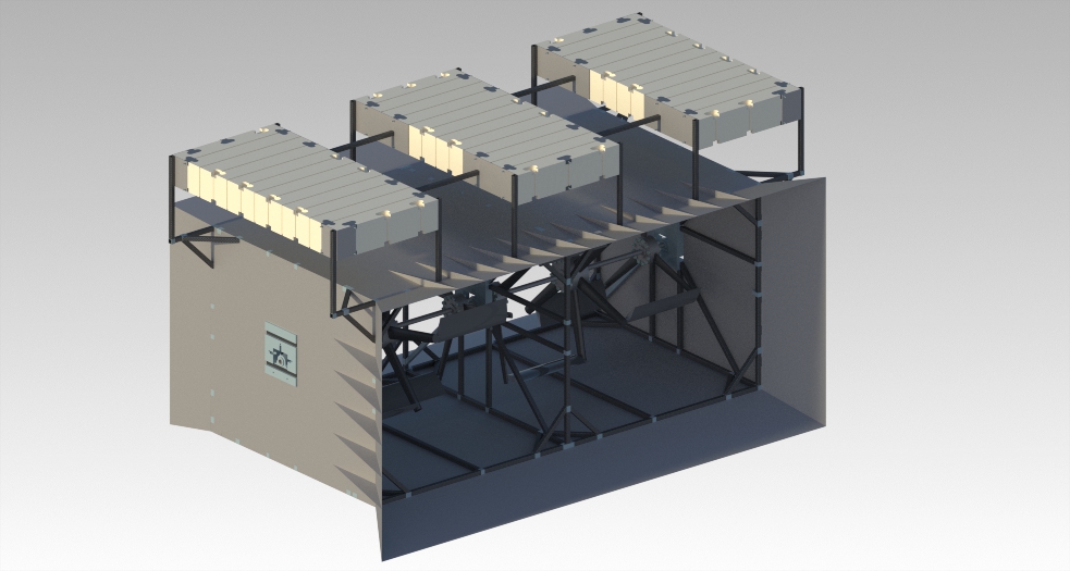
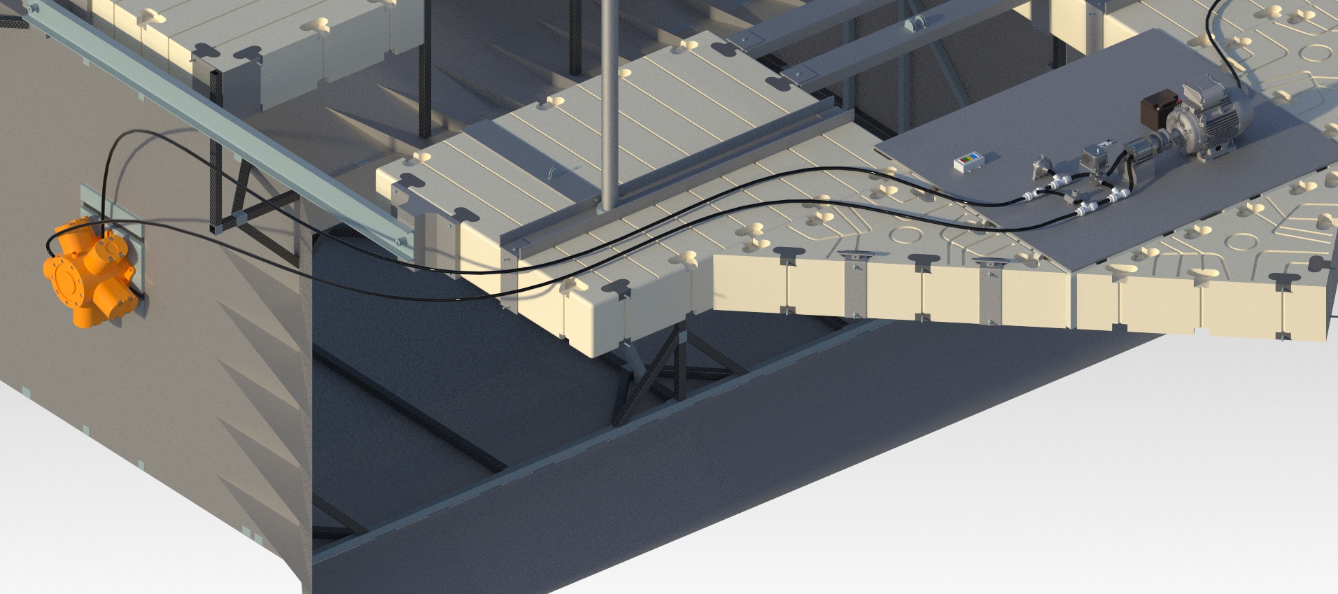
- 16 ft x 7 ft x 7 ft hollow frame using Weldments and custom bead patterns to support the turbine & generator system with a maximum load of 38,000N or 8,400lbs.
- Maximum Displacement = 4.8 mm or 0.188 in
- Minimum Factor of Safety = 5.1
-
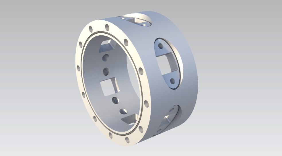
Multi-profile cam developed with MATLAB & Python to achieve precise angular variations in response to varying environmental factors
-
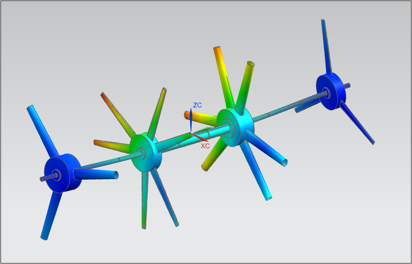
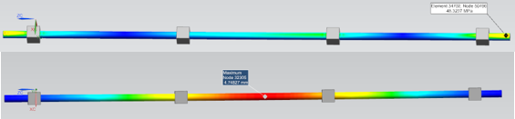
Telescoping rotating and non-rotating central shaft to deliver torque to a radial pump while supporting the weight of multiple rotating turbine sections
-
Internally-ribbed carbon fiber reinforced composite NACA airfoil designed and tested to withstand hydrostatic pressure and torque
-
Replacements of multiple key stainless steel components with carbon fiber composites to reduce weight by 40% and improve critical weight-to-stiffness ratio
- Multibody FEA to reduce bending of central torque transmission shaft